


Video Wall Mounting: Planning, Fastening and Installation in B2B
In B2B video wall mounting, projects rarely fail due to the display technology itself, but rather at interfaces: load-bearing capacity of the building structure, clear responsibilities between construction, electrical, IT, and AV teams, as well as an installation that remains maintainable and approvable in operation. Those who clarify these points too late risk redesigns, schedule delays, unclear operator responsibilities, or avoidable downtime.
Three questions are particularly decision-relevant: Is the substrate approved for loads and fastening points? Is the mounting and service concept planned so that module replacement and maintenance are possible without disproportionate effort? And are power supply and signal routing compliant, documented, and suitable for certification?
This article explains the planning priorities, typical interface challenges, and how to structure responsibilities so that the LED wall becomes a reliable communications interface rather than a long-term source of problems.
Structural Planning and Fastening Concepts
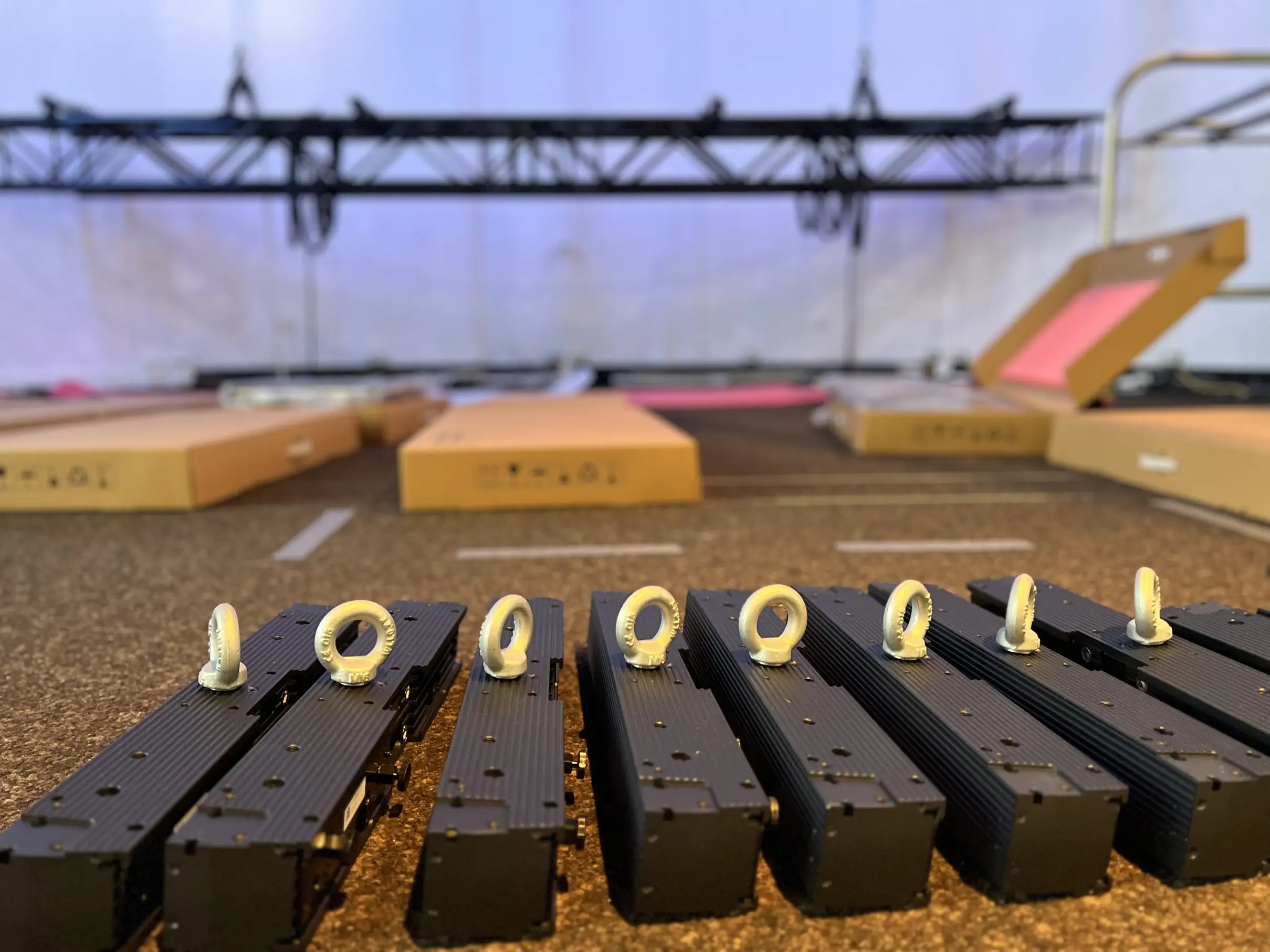
Load-bearing capacity is the foundation. Before any mounting planning, a structural engineer must confirm whether the substrate (concrete, steel, masonry, drywall) can handle both the panel weight and the dynamic forces from mounting systems, service access, and potential impacts. For indoor installations, this is straightforward; for outdoor or semi-outdoor systems, wind loads and thermal expansion must be considered.
- What is the total weight per square meter (including cabinetry, power distribution, and cooling)?
- Are point loads from individual anchors permissible, or must loads be distributed?
- What are the spatial tolerances for the mounting surface (flatness, surface regularity)?
- Are vibration damping or thermal expansion considerations required?
A best practice is to have the structural analysis document which mounting points can be used, with what torque, and in which order they must be installed to avoid uneven loading. This becomes particularly important during service: if a technician later has to replace a module and doesn't follow the documented sequence, alignment can shift, creating visible color or brightness jumps.
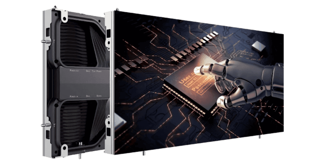
Common fastening systems include T-slot profiles, mechanical clamps, and magnetic holders, depending on module weight and installation depth. The choice affects not only installation time but also service accessibility. A principle worth following: design the mounting so that individual modules can be removed from the front without accessing the rear, if the installation depth allows it.
Multi-Disciplinary Coordination: Construction, Electrical, IT, AV
Even more important than technical specifications is clarity about responsibilities. Who checks the structure? Who approves the power routing? Who documents the cooling requirements? In many projects, these questions are not answered until installation is already underway, leading to unplanned halts and costly workarounds.
A proven approach is to create a simple responsibility matrix in the project plan covering construction/facility, electrical, AV/systems, and IT requirements. This prevents finger-pointing later and ensures that each party knows what is expected. Document decisions in a single installation plan that all stakeholders have signed off on.
Mounting and Service Concepts that Work
The best mounting concept is one that works not just for the initial installation, but for five years of service. Accessibility, documentation, spare parts strategy, and repeatability are all critical elements. Can modules be reached without shutting down the entire system? Are there as-built drawings showing module positions, serial numbers, power distribution, and signal routing? What is the spare parts strategy?
If a module fails and is replaced, the result should look identical to before. This requires either a documented calibration process or a strategy for accepting small color differences. The choice should be made upfront, not discovered during a service call.
Power Supply, Cooling, and Climate
LED walls consume significant power, and the infrastructure must be designed accordingly. Common oversights include insufficient power capacity, inadequate cooling, improper cable sizing, and lack of redundancy. Peak consumption (all modules at maximum brightness) is often much higher than typical operating load. LED modules generate heat, and insufficient cooling shortens lifespan and creates hot spots with visible color shifts. Long cable runs result in voltage drop that can affect color accuracy. In critical installations, consider dual power feeds and hot-swappable power supplies.
Thermal management should be part of the design, not an afterthought. Simulate typical operating conditions and determine whether passive cooling is sufficient or if active cooling (fans) is needed. If fans are required, they must be accessible and their noise level acceptable for the operating environment.
Signal Routing and Future-Proofing
Signal paths should be simple, well-documented, and designed for change. Centralized control, separated concerns, proper cable management, and thorough testing are key principles. Label every cable at both ends and use separate conduits for power and signal to minimize interference. Document the signal flow with a marked diagram before final approval. A simple network diagram, printed and laminated, hung near the controller, saves hours of diagnostic time later.
Commissioning, Handover, and Documentation
The handover from installer to operator is critical. Too often, documentation is minimal, leaving the operator with no understanding of what to do if something goes wrong. A thorough handover includes as-built drawings, tailored operating manual, troubleshooting flowchart, support information, maintenance schedule, calibration data, and training for regular operators. For larger systems, a spare parts package reduces downtime when minor failures occur.
Common Pitfalls and How to Avoid Them
Underestimating space requirements: LED walls need cooling, cable space, and service access. Installing one too tightly creates problems that cannot be solved later. Ignoring environmental factors: Temperature, dust, vibration, and sunlight all affect performance. Unclear maintenance responsibility: If no one is assigned to care for the wall, it will fail at the worst time. Missing documentation: Undocumented mounting and signal paths create confusion during service. Improper capacity planning: Power and cooling should allow service without shutdown, often requiring 20-30% reserve capacity.
Conclusion
Professional video wall mounting is more about planning and coordination than technical sophistication of the LED modules. By investing upfront in proper structural analysis, multi-disciplinary coordination, accessible mounting design, and thorough documentation, you create a foundation for reliable operation over years. This reduces service costs and downtime while protecting the investment value and ensuring the LED wall becomes a dependable communications tool.