


Whether in a control room, conference room, showroom, or retail environment, a video wall is often a central display and decision-making medium in B2B contexts. Precisely for this reason, even small differences between modules quickly become problematic. When brightness, white point, or color reproduction visibly "jump" between panels, readability decreases, installations appear imprecise during acceptance tests, and operations often experience recurring service issues or complaints.
Typical practical questions include: Is "calibrated from the factory" really sufficient? Which measurement method is reliable enough for acceptance and SLA requirements? And how can we ensure that module replacement later does not appear as a visible "patch" on the display? Those who understand calibration only as an initial startup check underestimate drift from temperature, operating time, and signal processing, thereby shifting costs and effort into operation.
Calibration is not a cosmetic step but a defined process with target values (e.g., white point, gamma/EOTF, luminance), measurement methods, documented results, and a strategy for restoration after service events. This article shows how to properly calibrate video walls or organize them internally using practical methods, common pitfalls, and selection criteria for decision-makers.
Why Calibration is Essential for Video Walls
Consistent image quality means that transitions between panels are not perceptible as brightness or color shifts at normal viewing distances. At least three parameters must be stably maintained: luminance (brightness), chromaticity/white point (color temperature and tint), and tonal range (gamma or EOTF).
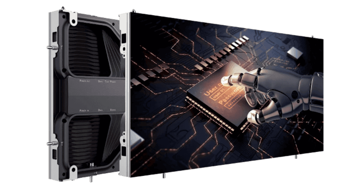
For LED walls, the display depends not only on the LEDs themselves but also on scan parameters, dithering, bit depth, mapping, and internal processing in the sender/controller.
Without calibration, a "patchwork" effect quickly emerges where individual modules appear cooler or warmer, dark areas are spotty, and gray gradients show banding or color casts. Especially with corporate content (CI colors), deviations are immediately visible because logos and brand colors are expected to be highly precise.
In control rooms or conference spaces, an uncalibrated wall further degrades information intake. Text and fine lines lose contrast, and eye fatigue increases when the eye must constantly adapt between areas of different brightness.
A common misconception in procurement is that "factory calibrated" guarantees permanent uniformity. In practice, factory calibration is often a starting point that is relativized by transport, installation conditions, power supplies, temperature management, and operating time drift. Additionally, modules are not always delivered from a single LED bin/batch, and tolerances exist even within a batch.
For B2B decision-makers, it is important to define calibration as part of the operating strategy. Typical trade-offs include maximum brightness versus lifespan, "punchy" display versus color-accurate reproduction, and quick commissioning versus reliable acceptance.
Calibration Methods: Visual, Sensor-Based, Camera-Based, and Controller-Based
In practice, three basic approaches have established themselves, which are combined depending on quality requirements and budget: visual calibration, sensor-based point measurement, and camera-based area measurement. Additionally, controller-based methods (LUTs, module correction data) provide technical implementation but do not replace clean measurement and target value definition.
Visual Calibration uses test images, grayscales, color fields, and the experienced eye of technicians. It is quick and can reduce gross deviations but is not reproducible and heavily dependent on ambient light, viewing angle, and individual color perception. For temporary installations or as "first aid" after module replacement, it can be useful; for B2B acceptance, it is typically too risky alone.
Sensor-Based Point Measurement uses colorimeters or spectroradiometers to record white point and primary colors at defined measurement points. Advantage: objective measured values and the ability to define target values like D65 or customer-specific white points. Disadvantage: point measurements do not automatically capture the entire surface; for very large walls, the effort increases if many panels must be individually measured.
In practice, a representative point grid is often chosen, combined with manufacturer data per module.
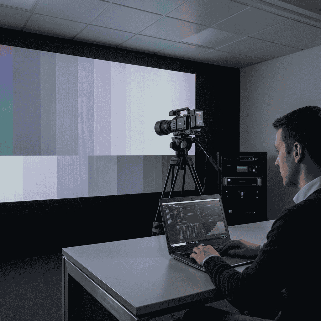
Camera-Based Calibration measures the entire LED wall in a distributed manner and detects brightness and color deviations across all panels. This is particularly effective when many modules are involved or when mura effects (cloudiness, spotting) should be reduced in dark tones. Important is the quality of the camera system, the camera's own calibration, and controlled measurement conditions (distance, angle, stray light).
Controller and LUT-Based Methods are the link between measurement and visible result. Modern LED controllers work with correction matrices and lookup tables (LUT) to compensate for deviations per module or even per subpixel. Critical here is the granularity of correction (module, cabinet, pixel) and the color depth of processing so that corrections do not result in banding.
Best Practices: Target Values, Measurement Setup, Process Plan, and Acceptance Criteria
Reliable calibration begins not with a measuring device but with defining target values. B2B projects benefit from a brief, written calibration and acceptance plan integrated into project planning. It specifies the desired white point (e.g., D65 or D55), target luminance (e.g., 300-600 cd/m² indoor, significantly higher for semi-outdoor), gamma/EOTF (e.g., 2.2 or 2.4 depending on use), and color space (usually Rec.709 for classical content).
The measurement setup must be reproducible. This includes a defined viewing angle (preferably orthogonal), fixed measurement distance, controlled ambient light, and a thermally stable wall. LED systems change during warm-up: a good process includes a warm-up phase (e.g., 30-60 minutes) before final measurement and correction.
In critical environments like control rooms, operation often occurs at reduced brightness; calibration should then also occur at this operating brightness, not at a laboratory maximum value.
A proven process plan consists of four steps: First, check the signal path for errors. Second, align luminance uniformity, since brightness jumps are more noticeable than small color differences. Third, align white point and primary colors, ideally per cabinet/module via the controller. Fourth, validate with actual content and standardized test sequences.
Acceptance criteria should be measurable and understandable. Tolerances for luminance uniformity (e.g., percentage deviation across surface) and color differences (e.g., DeltaE) are agreed upon. Importantly, criteria fit the application: a display wall in a bright foyer needs different tolerances than a control room where grayscale backgrounds and fine details are observed over hours.
Operation and Maintenance: Drift, Module Replacement, Ambient Light, and Service Routines
LED walls do not remain "once calibrated, always correct." LEDs age depending on operating hours, temperature, current density, and displayed content, shifting luminance and sometimes color point. Dust, filter condition, fan curves, and climate also affect temperature management and stability.
A common service issue is single module or cabinet replacement. Even when spares come from the same manufacturer, binning and production timing can differ. Without access to correction data or re-calibration, the classic "patch" effect occurs: one panel appears brighter, cooler, or has different saturation.
Best practice is a spare parts concept including calibration data. After replacement, apply the correct correction profile and validate with a quick check or ideally with full surface measurement.
Ambient light is also often underestimated. In retail or foyer situations, a wall can receive significantly more ambient light during the day than in the evening. If the wall then adjusts only luminance via a brightness sensor but does not account for color behavior, visible differences emerge throughout the day.
In B2B installations, multi-profile operation often pays off: for example, a daytime profile with higher luminance and an evening profile with optimized near-blacks and reduced glare potential.
From an operational standpoint, two routines pay off: regular short visual and measurement checks and periodic full calibration. Quick checks use standardized test images and few measurement points to detect drift early. Full calibration is less frequent but includes complete surface measurement and documentation. For 24/7 environments like control rooms, proactive maintenance is cheaper than reactive service because downtime and coordination effort exceed the actual calibration effort.
Frequently Asked Questions
How do I integrate calibration into SLAs so re-calibration becomes plannable?
Define clear triggers in the SLA such as specific drift values in luminance distribution, a number of module replacements, or measurable DeltaE deviations. Specify who is responsible for providing and implementing correction data and how quickly quick or full calibration must occur after a trigger. Document response times, validation steps, and acceptance criteria so operations remain transparent.
What are minimum requirements for measurement hardware in B2B calibration?
Use calibratable devices that reliably capture the relevant color space (e.g., Rec.709 or DCI-P3) and are scalable to the desired target brightness. Spectroradiometers offer higher accuracy, while colorimetric cameras are useful for area measurements if themselves regularly referenced. Important: defined measurement distances, viewing angles, and a stable warm-up state.
How do I handle module replacement without visible "patches"?
Maintain module and cabinet serial numbers with position mapping in a spare parts concept so correct calibration profiles are known after replacement. Apply corresponding LUT data and validate with a quick check or ideally a surface measurement. Document the process with checklists and logs so integrators and operators know how quickly uniformity is restored.
What is the difference between quick-check and full calibration in the process?
A quick-check uses few representative points or standardized test images to detect drift early and can occur frequently with minimal effort. Full calibration covers the complete surface with documented target values and correction on controller or LUT level, typically at longer intervals. A sensible combination is regular quick-checks with semi-annual or annual full calibration depending on operational demands.
Conclusion
Consistently calibrated video walls are not just an optical matter but an operational and economic lever: they reduce complaints, speed up acceptance, simplify service, and protect the investment over its lifetime. Essential are defined target values, appropriate measurement methods, and repeatable processes with documentation. For B2B decision-makers, it is worthwhile to anchor calibration early in specifications and SLAs with measurable criteria, a plan for drift, and clear procedures for module replacement. This keeps the LED wall a reliable medium over years instead of becoming a persistent error source.